Adapting an XR front footpad for a Fungineers controller box
I love the Fungineers controller box (fungibox), but I also love the original XR front footpad. To use them together, some changes to to footpad are needed.
- The cable has to run from the center to the right of the board, and also it has to be a bit longer to reach that far.
- The status LEDS require a hole in the footpad, exactly in the location where the sensor cable normally is, so this calls for some drilling and rewiring.
Plan
This is the third footpad I’m customizing this way. The first one works fine, but was a little messy, and on the second one I accidentally destroyed the printed wiring on the plastic lip of the sensor. And so I decided to make a more solid plan this time, and work with more precision, and share it for others planning the same job.
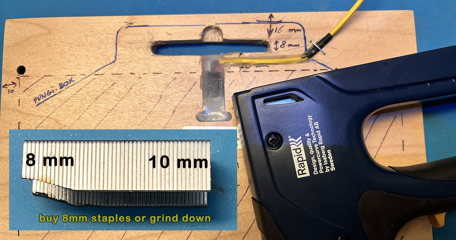
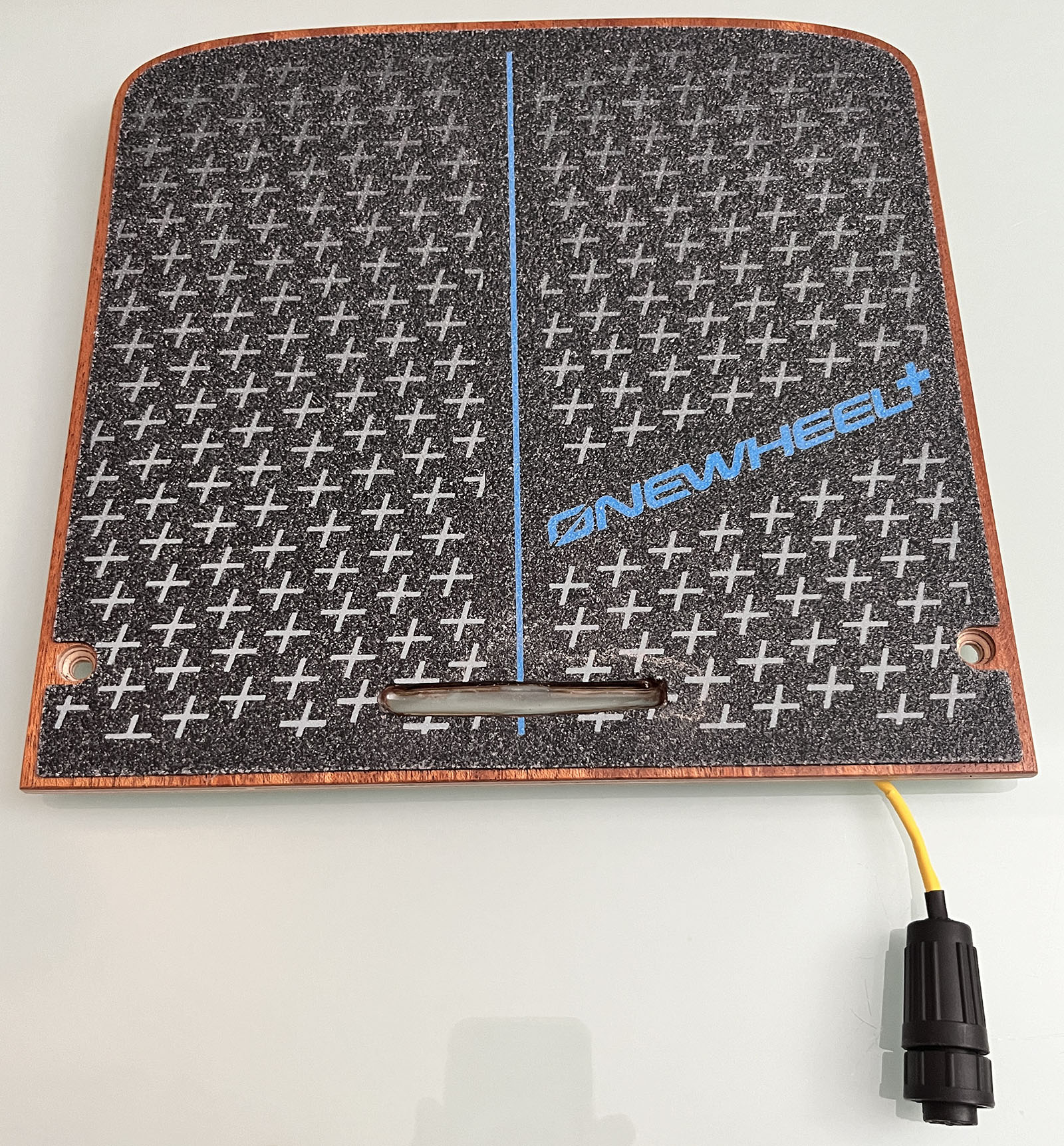
This image shows the plan for holes and wiring:
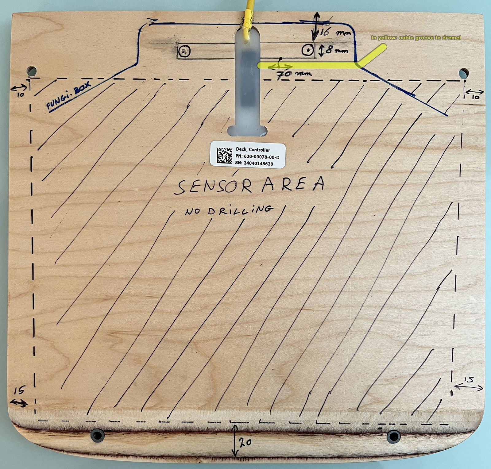
The bent yellow line is where we will Dremel a groove for the sensor cable. This only has a be some 3-4 mm deep, so it doesn’t affect the stability of the footpad, especially since most of the groove is supported by the fungibox (see solid contour line).
The 8x70mm rectangle will become a hole for the status LEDs. It overlaps with the XR wiring channel, so we have to rewire that to the new yellow groove, which is a very tight job – that’s why I messed up my second attempt.
Remove XR wiring
The XR wires are kept in place by hot glue, which can be melted at a fairly high temperature. I use a soldering heat gun at 300°C for this purpose, as it allows for precise heating, without melting the cables and connectors. It’s a job that takes some patience. The glue doesn’t have to become completely fluid. AT some point it will get soft enough the wiggle the cable and both connectors out of the channel. After that, you can remove the rest of the still warm glue with a screwdriver.
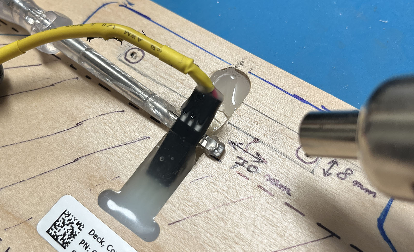
Hot glue gets soft and connectors can be pried up
Clean the glue from the male connector while it’s still warm
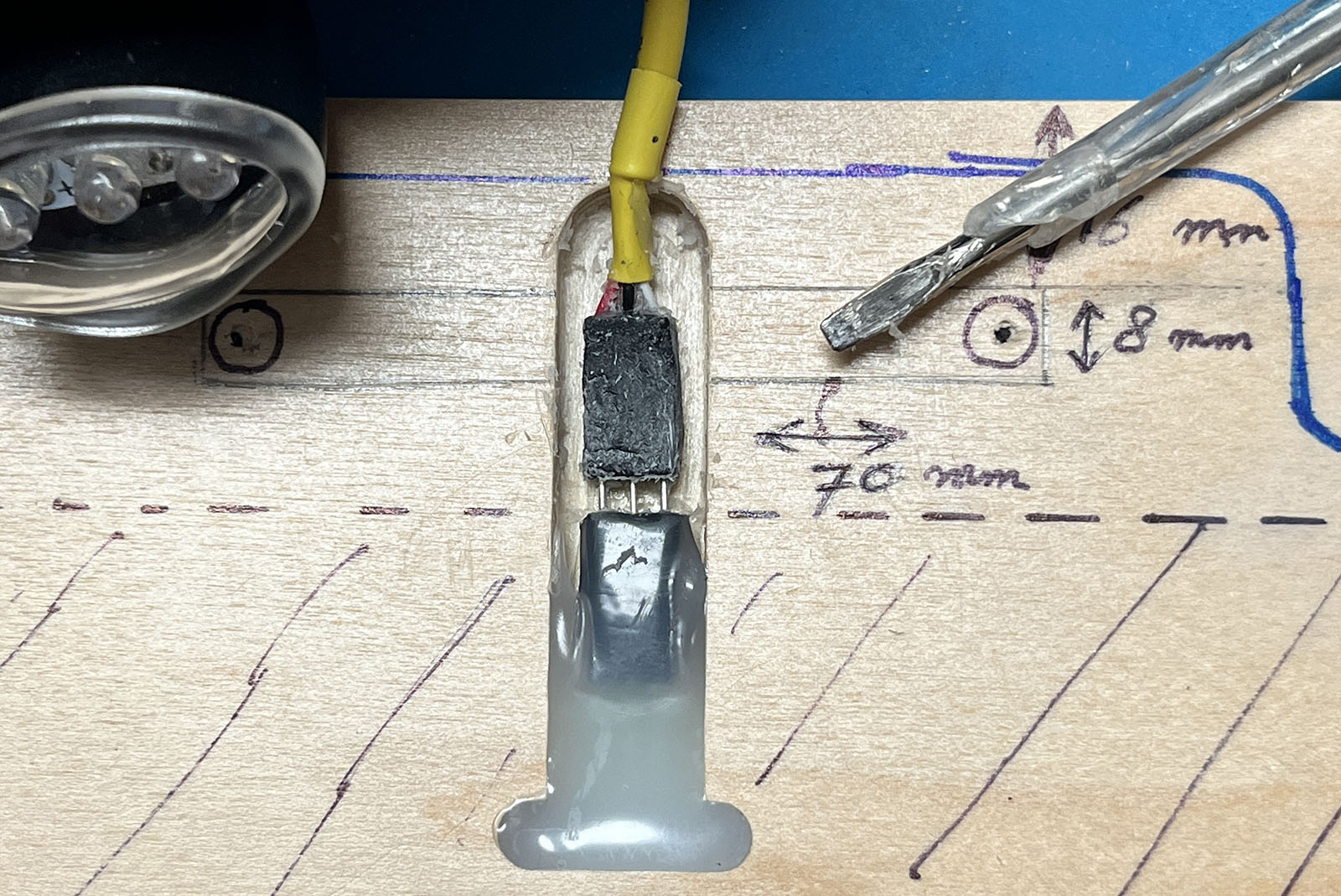
Create window for LEDs
In the rectangle for the LEDs, you can see two small circles, which I start creating the window with a drill ( I use a 7mm drill to make sure the holes don’t get too wide). Be gentle on the last millimeters if you want to get a clean cut through the grip pad. After that, I use a Dremel with a disk cutter to cut the straight lines of the window. Always use eye protection for this kind of job – on this job alone I had disks break and fly around. To avoid breaking disks, never use force or wiggle the disks to make it go where it has to. I the direction is slightly off, start again with a better angle. Again, no force! When the disk starts slowing down, you’ve reach the glue layer of the grip pad, so you’re almost through.
If you don’t have a Dremel, you can also drill 10 holes of 7mm each, and remove the rest be filing and cutting. Or you can even leave the 10 holes visible – after all, the status bar has exactly 10 LEDs, so that might look kind of cool, and the epoxy resin doesn’t care which shape it should flow into.
Turn the deck pad around and try to make a nice finish for the edges of the grip tape that you drilled and cut into.
Dremel cable groove
There are more specialized tools for making cable grooves, but I found those too expensive, so I used a sharp knife to cut a v-groove first, and then a small Dremel sander to make it a bit deeper and rounded.
Extend cable
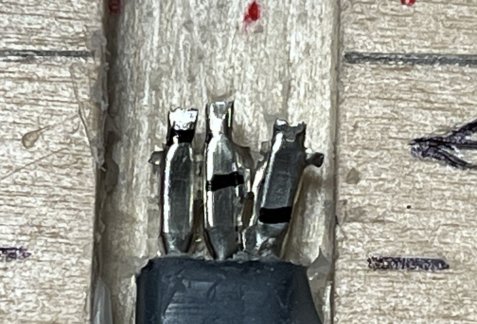
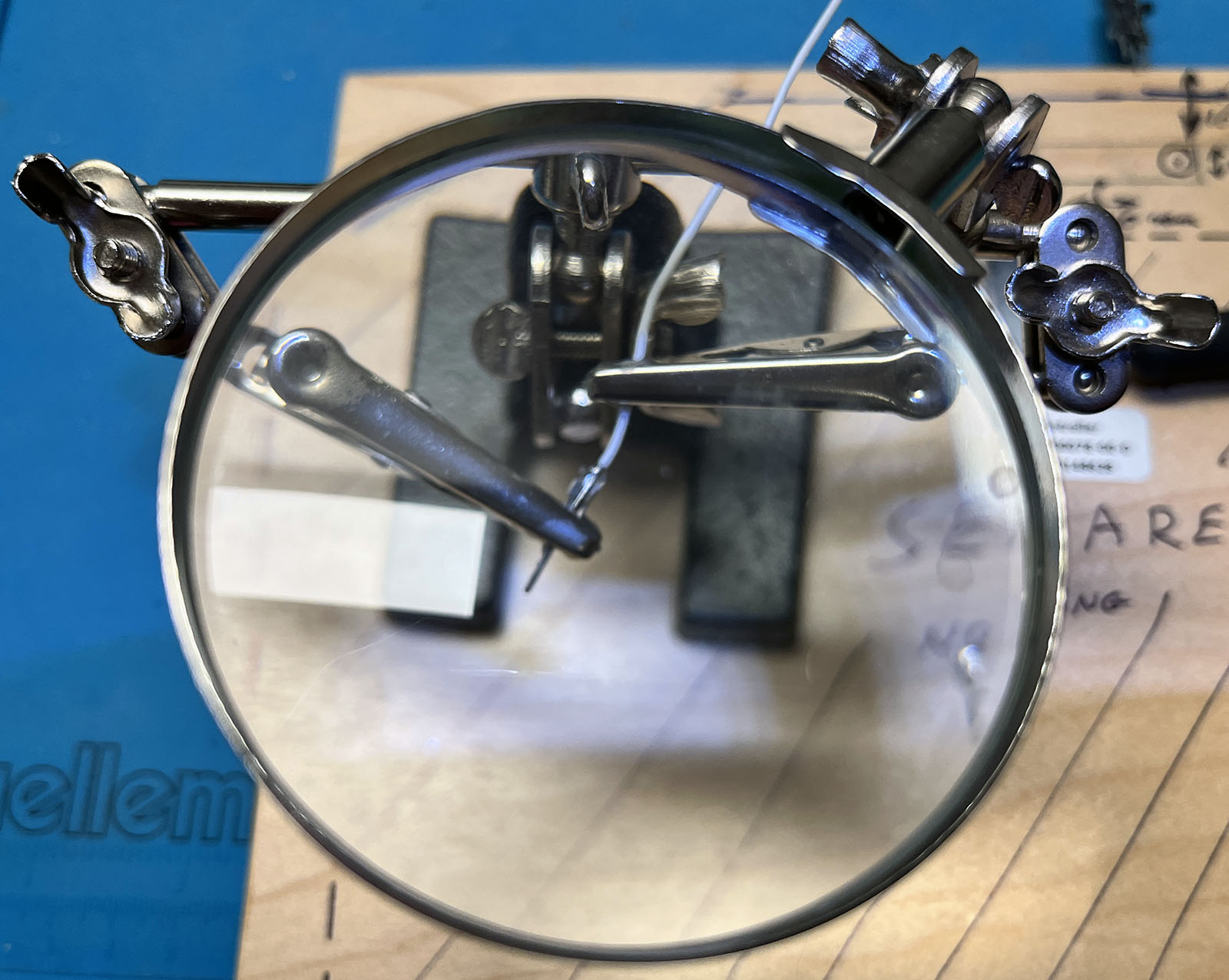
Since there is hardly any room between the female plug attached to the sensor and the cable groove, this part is very tricky. I cat the male plug into 3 pieces, remove the rest of the plastic, and solder the pins directly to the new wires. From left to right, the pins will have to be a bit shorter to make it all fit into that tight 90° corner. Each wire needs some tiny heat shrink plastic to avoid contact between them. This is the most precise part of the job, and I typically use watch maker glasses to do it.
The three pins in the next photo are what’s left of the male connector after removing the plastic housing. I plugged them in and marked where each one should be cut in order for all three wires to have space to bend towards the new wire groove.
The next photo show how the pre-crimped JST-GH wires (15 cm) are soldered to the male pins. Did I already mention that this is a precision job? Make sure you have a soldering iron with a really fine tip.
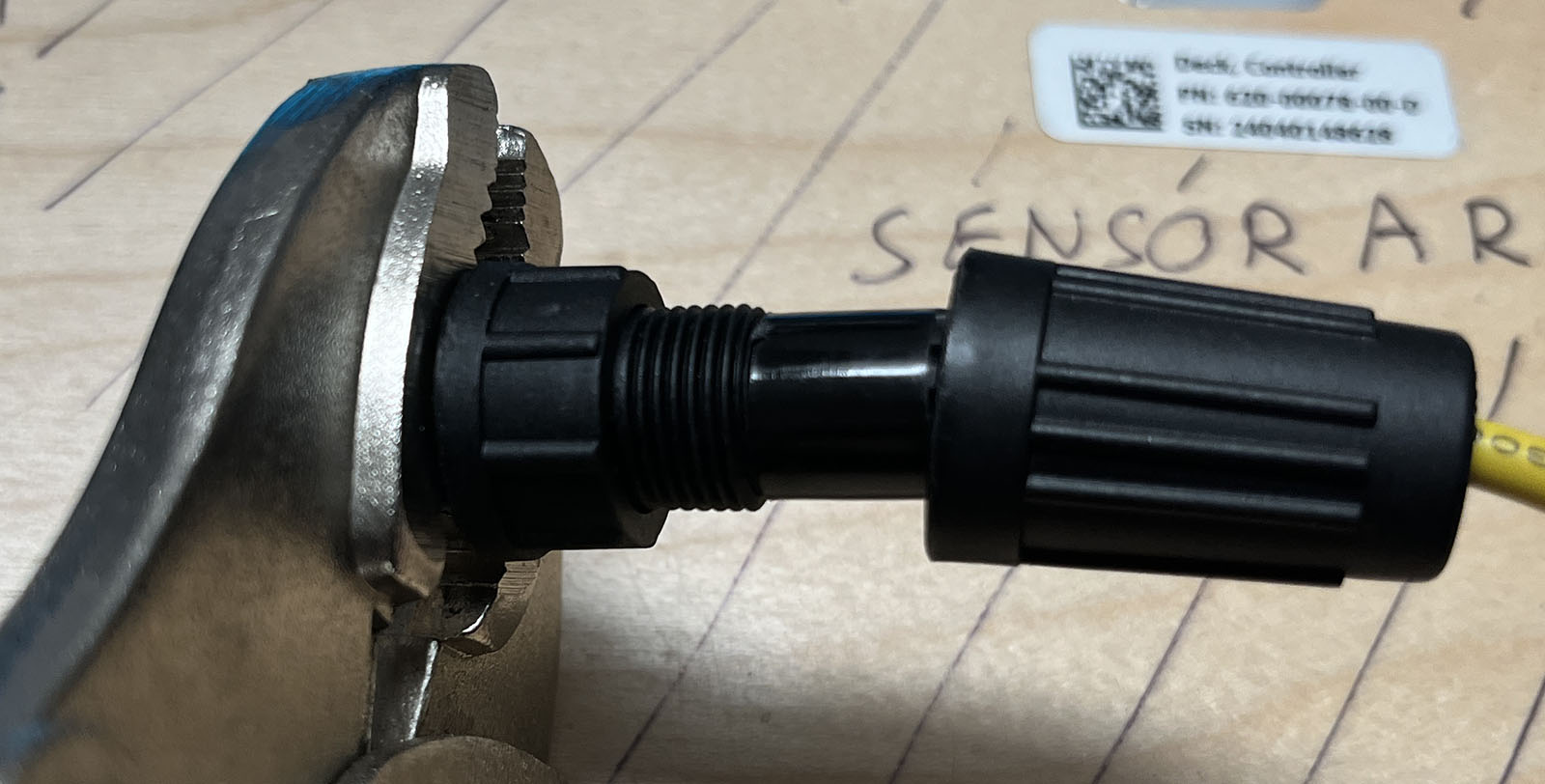
The end result looks like this:

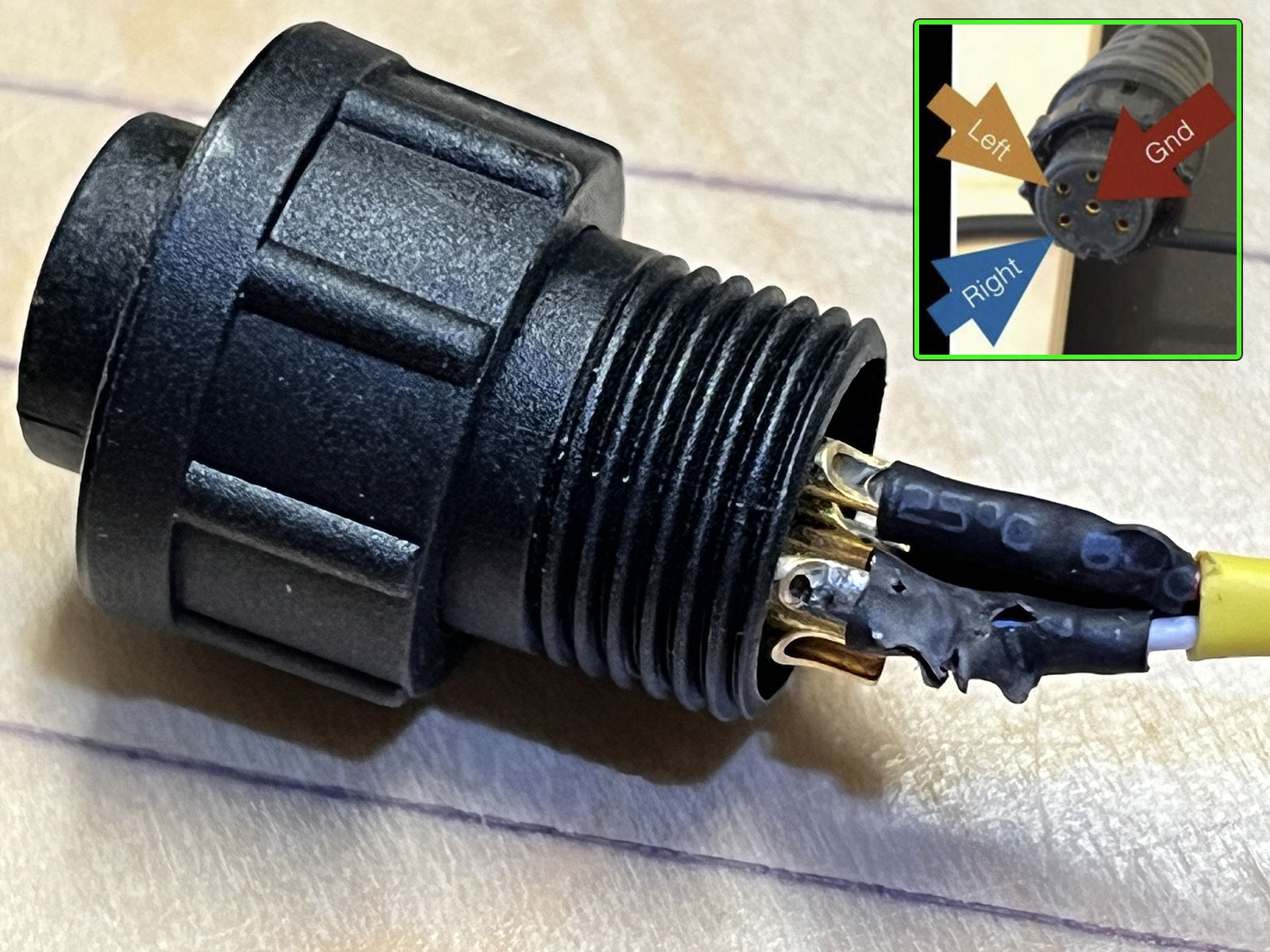
The other ends of the wire are soldered to the old XT plug. Take the plug apart first (screw the lid off):
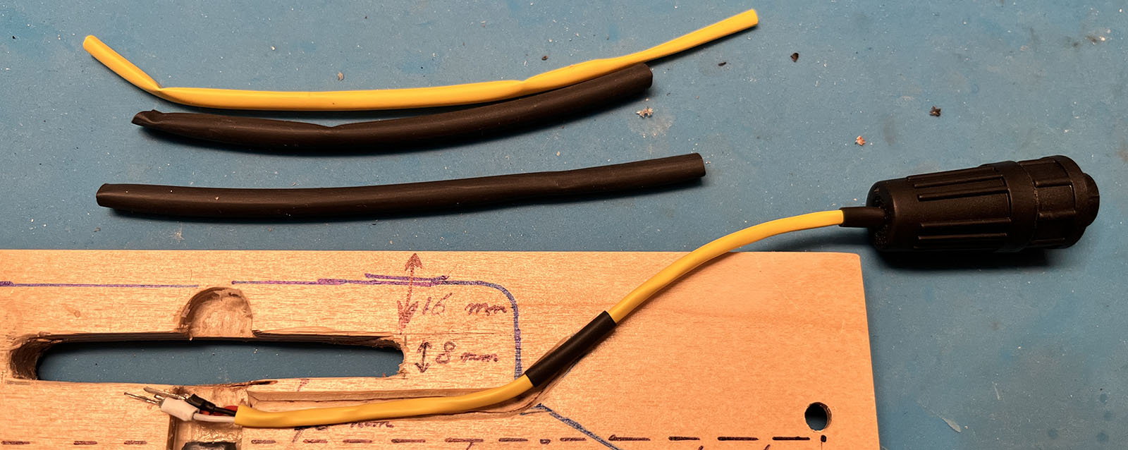
Before soldering the plug to the wires, add some heat shrink to make the cable more stable (the tiny JST-GH wires are really fragile). I shrunk that yellow tube and added two pieces of black heat shrink tube: one for extra stability in the gland of the connector, and one to protect the area where I will use the staple gun later.
And then unsolder the old wires. Try to get the copper channels clean of soldering tin, then the tiny crimped connectors fit in there exactly, which makes them easy to solder.
Now you can close the plug again.
Attach cable
Plug in the 3 connectors, and add something to the LED window, to keep the hot glue from running there. I used a spaces, a flat piece of metal sheet, and a piece of baking paper (doesn’t stick to hot glue).
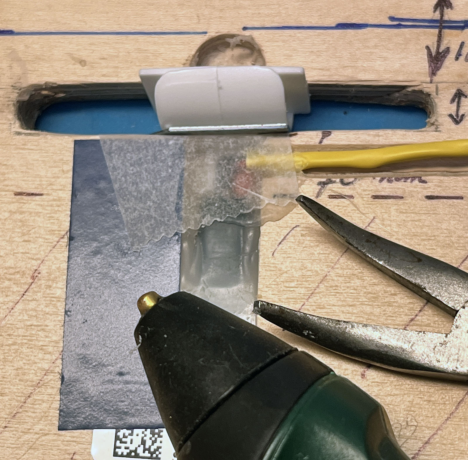
I used a small portable hot glue gun from Bosch for this, as gives more precision. To effectively fill final gaps, especially between the yellow cable and the groove, using baking paper again. Wear a thin glove, put the hot glue on, and immediately put baking paper over it, and then push it in and flatten the surface with a gloved finger.
Finally, I used a staple gun to secure the cable across the black part, which is just outside the Fungineers box. My staple gun as on the lightest setting, and I needed 8mm staples, to make sure they would pierce the complete foorpad and grip tape. Since I couldn’t find those in the hardware store, I did some grinding.
Fill LED window
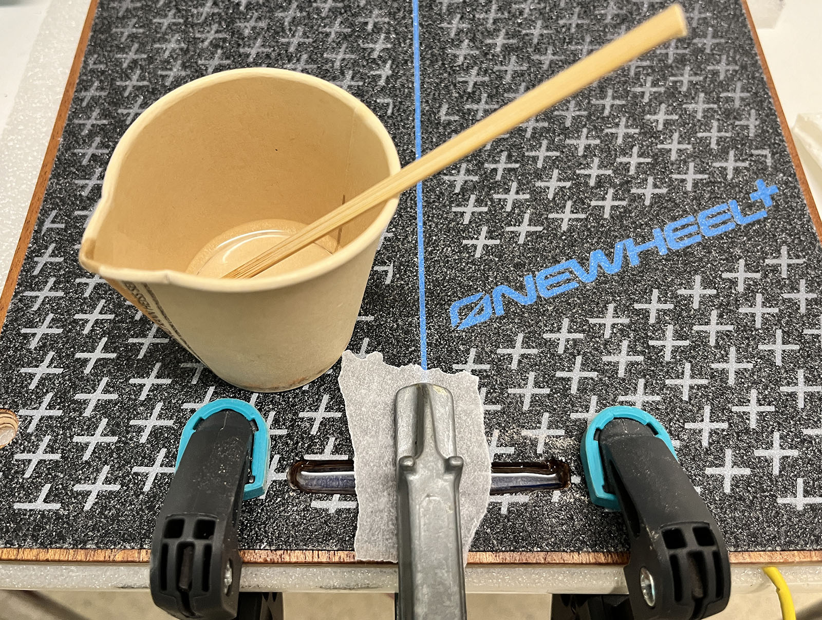
Finally, it’s time to fill the LED window with 2-component epoxy resin. What can go wrong here is that the resin may trickle to place you don’t want it to go, and you will not notice that until it’s hardened, i.e. really difficult to remove. I am using electrical tape (with a piece of baking paper again where the bottom of the window is, to make it easier to remove).
I clamped the board to a table, and added a layer of foam between the table and the footpad, to make extra sure no resin could leak out. I added a clamp in the center as well. For a new footpad this is not really necessary, but if you’re using an old one, the grip pad glue may not be quite as tight, and resin can flow between the wood and the grip pad.
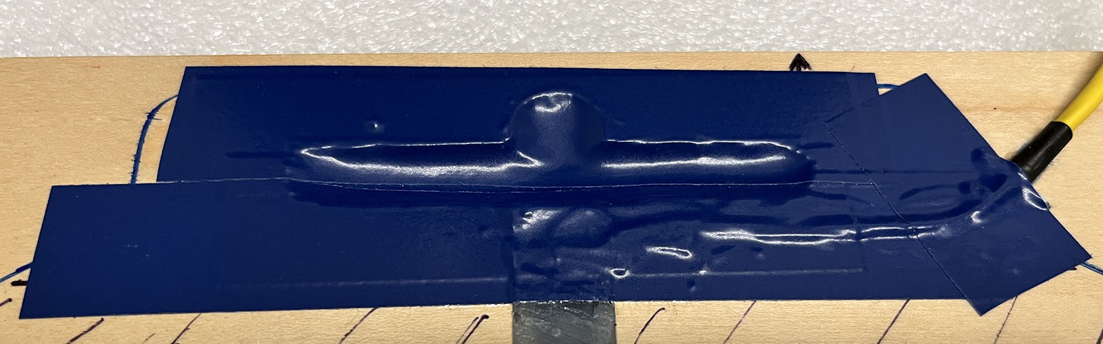
Poor in the resin, and wait for it to harden. After hardening, the back looks like this. You can clearly see how the foam made the resin a little concave.
Remove the tape and baking paper, and your new footpad should be ready to go.
The JST-GH wires are really thin, and although the are well protected in the yellow and black tubing, I do recommend to add 3D printed wire protectors for your Fungineers box.
Conclusion
It’s quite a job, I know. But I don’t trust the plastic lid of the Fungineers box to use soft or 3D-printed footpads without a metal plate, and adding a metal plate would probably make wifi and Bluetooth signals almost trapped inside the box. Apart from that, I really like the original XR footpads, so for me, it’s worth the trouble.
Some self-critique: yes, the shape of the window could have been a bit more regular, I know, but that would have taken a lot of extra cutting, filing and sanding. For me, functionality always comes first, so I sometimes run out of patience for meticulous jobs that only improve the cosmetics…
Used tools
For most tools used here, I’m assuming everybody has them in their own home or their neighbor’s. Some accessories are also easy to find at your local hardware store. I’m only listing a couple of products that are a bit more difficult to find at reasonable prices:
Soldering hot air gun. Search for that term on Amazon or Aliexpress. You’ll find them for $40 or even less.
Dremel. I used this cheap portable one from Aldi, which came with all the bits I needed: https://www.aldi-onlineshop.de/p/multifunktionswerkzeug-12-v-101014307/
Wires. I used pre-crimped 15cm JST-GH wires. I had bought a box of such wires and connectors on Amazon anyway, as the Thor300 uses JST-GH, and thus I needed to make an adapter for the remote UART cable and extra LEDs in my custom battery pack. The wires have a perfect length for a footpad connection, and the pre-crimped ends make them easier to solder, as they are almost too thin to even use a wire stripper. https://www.amazon.de/GH1-25-Crimped-Silicone-Compatible-Pixhawk-various-colours/dp/B07PBHN7TM
Heat shrink tubing. I used the yellow 3.2 mm and the black 4.8 mm version of this product: https://www.amazon.de/dp/B07C67T61D
3D printable wire protectors. There are some different version around, but here is the one by Fungineers: https://www.printables.com/model/853568-funwheel-box-cable-covers
 Bis auf weiteres gilt mindestens 2 Meter Abstand zwischen allen Teilnehmenden (inklusive Leiter). Der Abstand gilt vor, während, und nach Unterricht oder Tour (inklusive Pausen und Transport).