Why 16S2P
16S2P is my preferred setup, but it is not very common. I love saving some weight, and I don’t care about speed, so 16S is enough for me. Also, I love having more than enough space for the BMS. If you want to go 18S or 20S, it’s easy to adapt the process a little. For 18S, remember that this gives you an odd number (9) of cell pairs on each side, which means that the plus and minus side on one end are further apart than with an even number (16S, 20S).
If you insist on making an odd S pack, e.g. 17S2P or 19S2P, things get a bit more complicated, as you will have one 2P pair that either will make the pack asymmetric (one side of the pack will be longer), or has to be paired differently. I don’t recommend this.
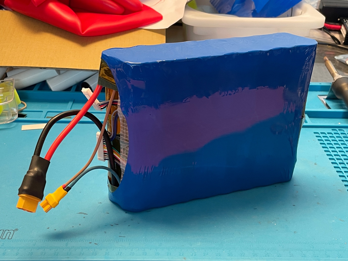
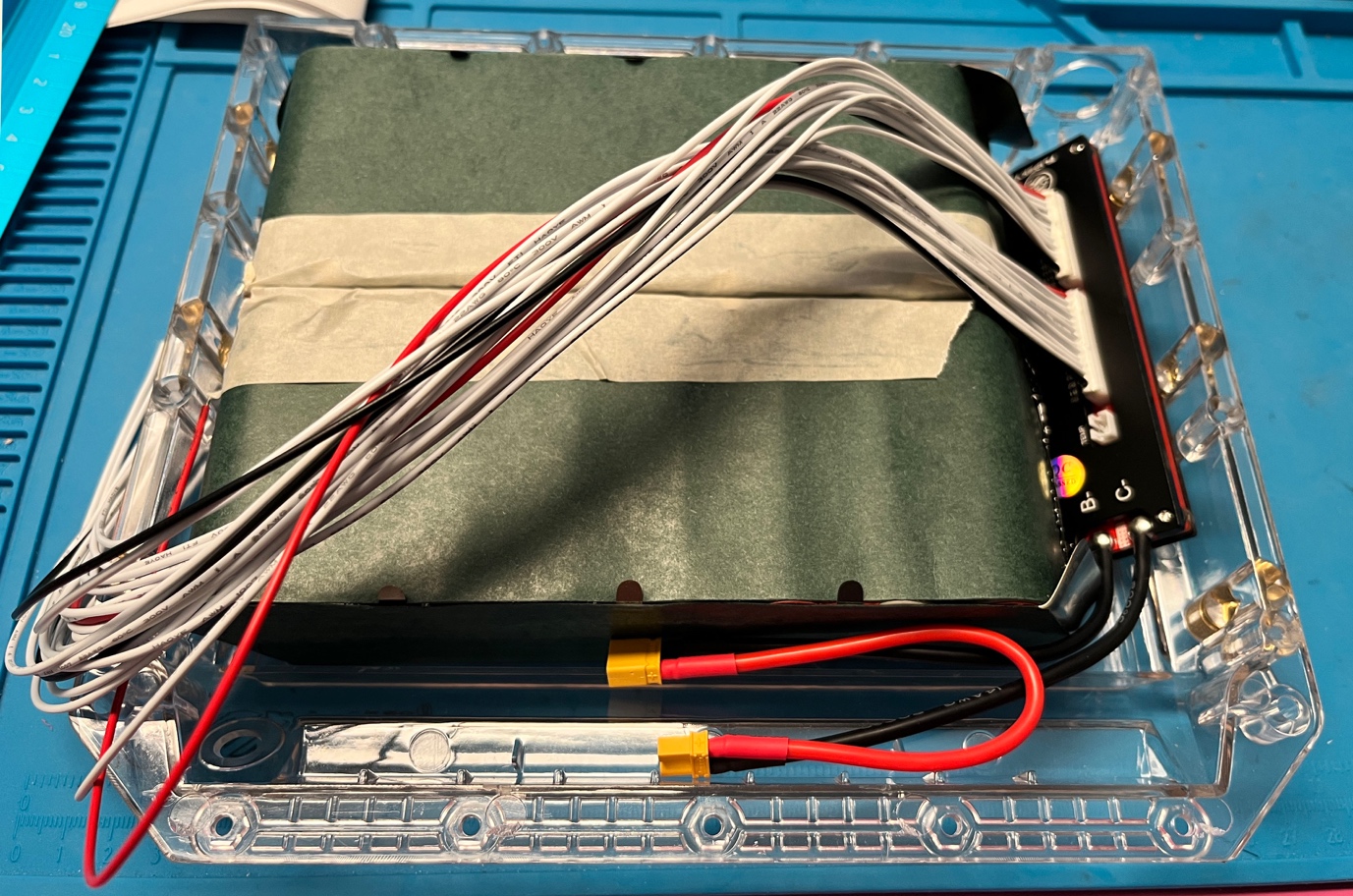
The photo above shows my first pack, which I built in 2023. The pack has the BMS on the side of the board, right between the main battery poles. In this 2024 pack, I decided to put the BMS in the back of the board. This results in longer BMS wires, but it leaves more room for the main connectors. Now that I finished my second pack, I think I liked the first approach a bit better, but that’s probably a matter of taste.
Caution
I am an engineer, and like to work very precisely, but I’m also nervous when there is danger involved in a job, and working with batteries at such high voltages is dangerous indeed. 84V from some batteries may not sound like much, but this is DC, which means it’s more dangerous than getting a quick shock from a 110V or 220V AC outlet. An AC shock makes you automatically pull back from the source of the shock, but that reaction does not occur with DC, any shock will last much longer, which makes DC more dangerous. So, make sure to never touch more than 1 pole at the same time, especially if your hands are wet or sweaty. I even bought protective electrician’s gloves, but they are thick and really difficult to work with on precision jobs like this.
I also made it a habit to measure the voltage between any two points before connecting them. If you measure anything above 0V between two poles, it’s a bad idea to connect them, let alone weld them together.
Tools
We need good tools to make a decent battery pack. I tried some cheap tools at first, e.g. a cheap spot welder from Amazon, but it’s not worth it, as the welds become too unreliable, and you’ll have to make a LOT of welds. A cheap hot glue pen didn’t help either, as the amount of glue it can apply per second just isn’t enough for the job. A list of all tools, materials, and 3D prints I used is at the bottom of this document.
Be aware that the financial overhead for all tools and materials are quite substantial, so if you plan to only ever make one pack, you may want to consider just buying a battery pack instead of making it yourself. I planned to only ever make one pack myself, but I love the challenge of such a project, and now that I’m starting a second pack, I also decided to write things down here, so others can avoid my initial mistakes.
Battery box
I recommend using the Torque Box for this setup, as 21700 batteries are too thick to fit in other boxes. Be aware that the Turque box also requires a Torque bumper.
Fish paper, 0.2mm thick:
- Make 70x40mm patches, and fold (away from the adhesive) into 15×70 and 25×70. These patches will isolate the 2P groups from eachother (even better: 70×35, folded into 15×70 and 20×70 – see below). The folding is to make them fit better on each 2P pair. You’ll need S-2 pieces of such patches, so in our case, 16-2=14 patches.
- Secure all plus sides of the batteries with a round piece of fish paper. This is to avoid the nickel plates from ever shorting the battery, even if the plastic insulation would melt.
Battery sorting
Sort the batteries by internal resistance. I used the XTAR Dragon VP4L Plus to measure the resistance, but there are probably other devices that make this easy as well. After sorting the batteries, make sure to use batteries with similar resistance in each 2P pair. I made my first pack without this sorting, and it works fine, but the sorting should improve the performance and longevity of the pack.
Making pairs
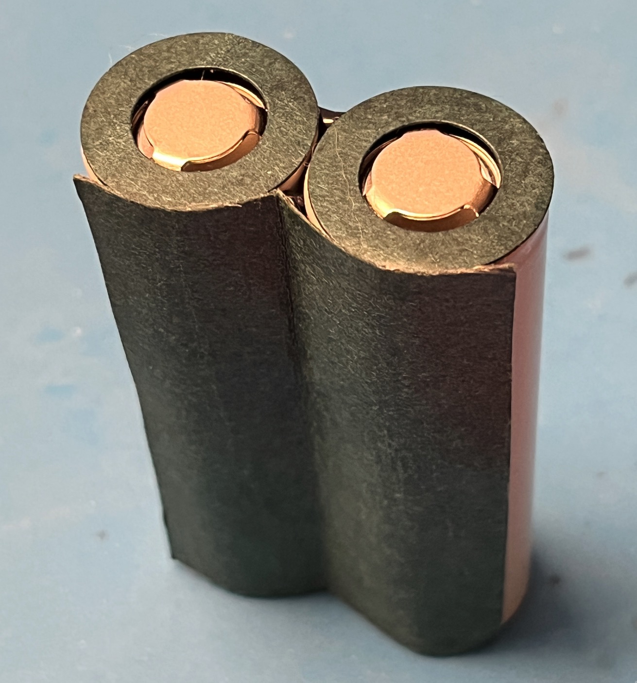
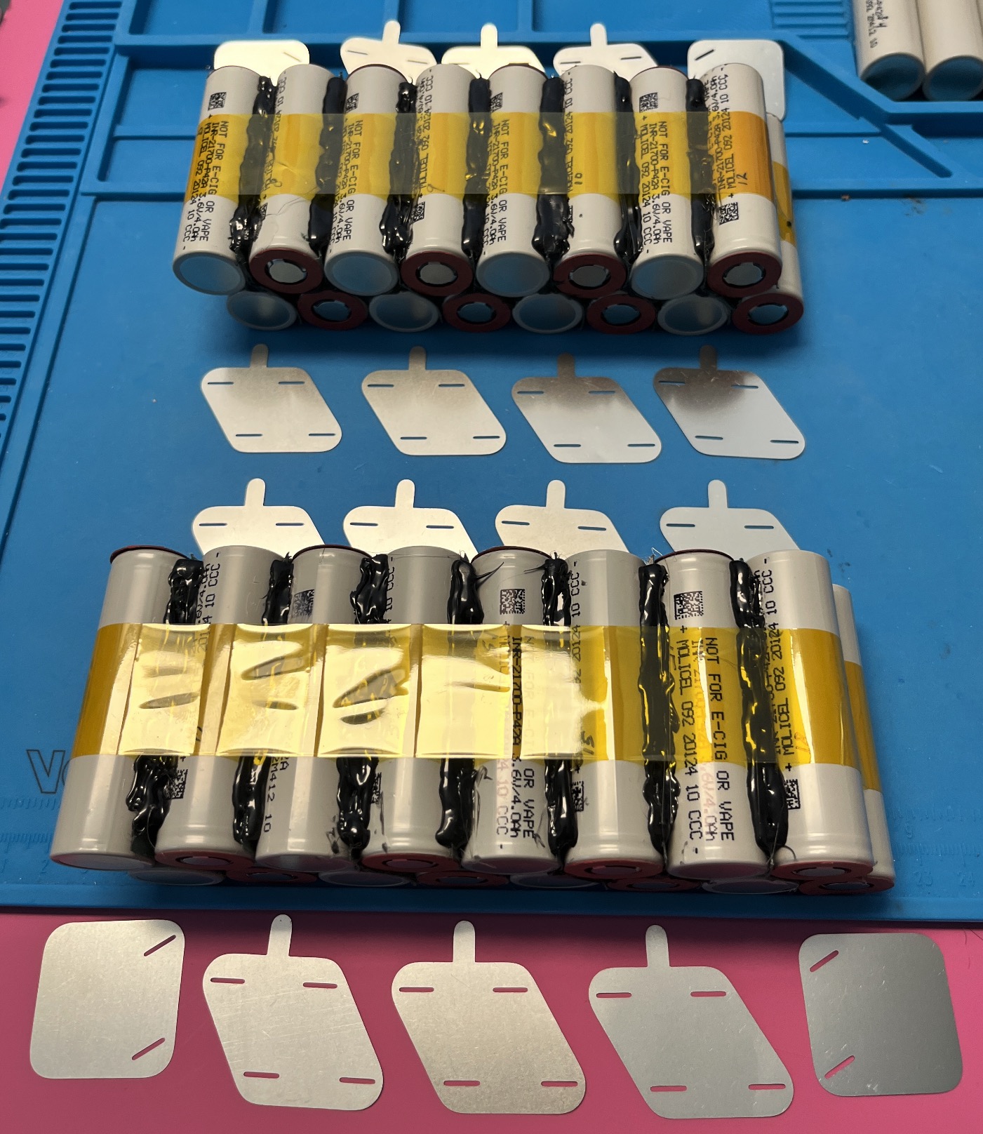
Align 2 batteries with similar resistance side by side, lying flat, and apply hot glue between them. I use black hot glue, as it’s easier to see where you already applied it, and how much. Let the glue harden, then turn the pair around. On this side of the pair, we will add glue, and also add the fish paper patch. Fold the patch once more to get a sharp fold, remove the adhesive cover, and set it aside. Now hot glue this side of the pair, and while the glue is still soft, put the fold of the fish paper patch into the glue. Give it some time to harden, and then stick the rest of the patch to the batteries. The result should look like this.
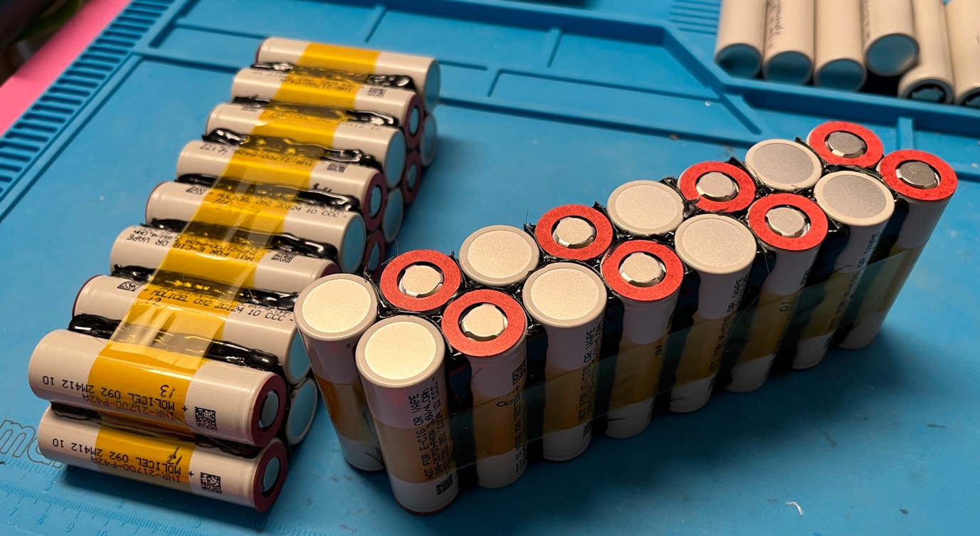
I use a 3D printed battery tray to make each pair. It’s not strictly needed, but it keeps the batteries aligned and in place during the gluing. The download at the bottom also includes a battery model, which I printed some 40 of, in 2 layered colors. Those help me visualize what the end product should look like. I’m pretty good modelling stuff in my head, but for this project it was just a bit too much. With all the cables and poles and pairs and BMS wires and weld plates in play, the fake batteries helped me a lot for my first build.
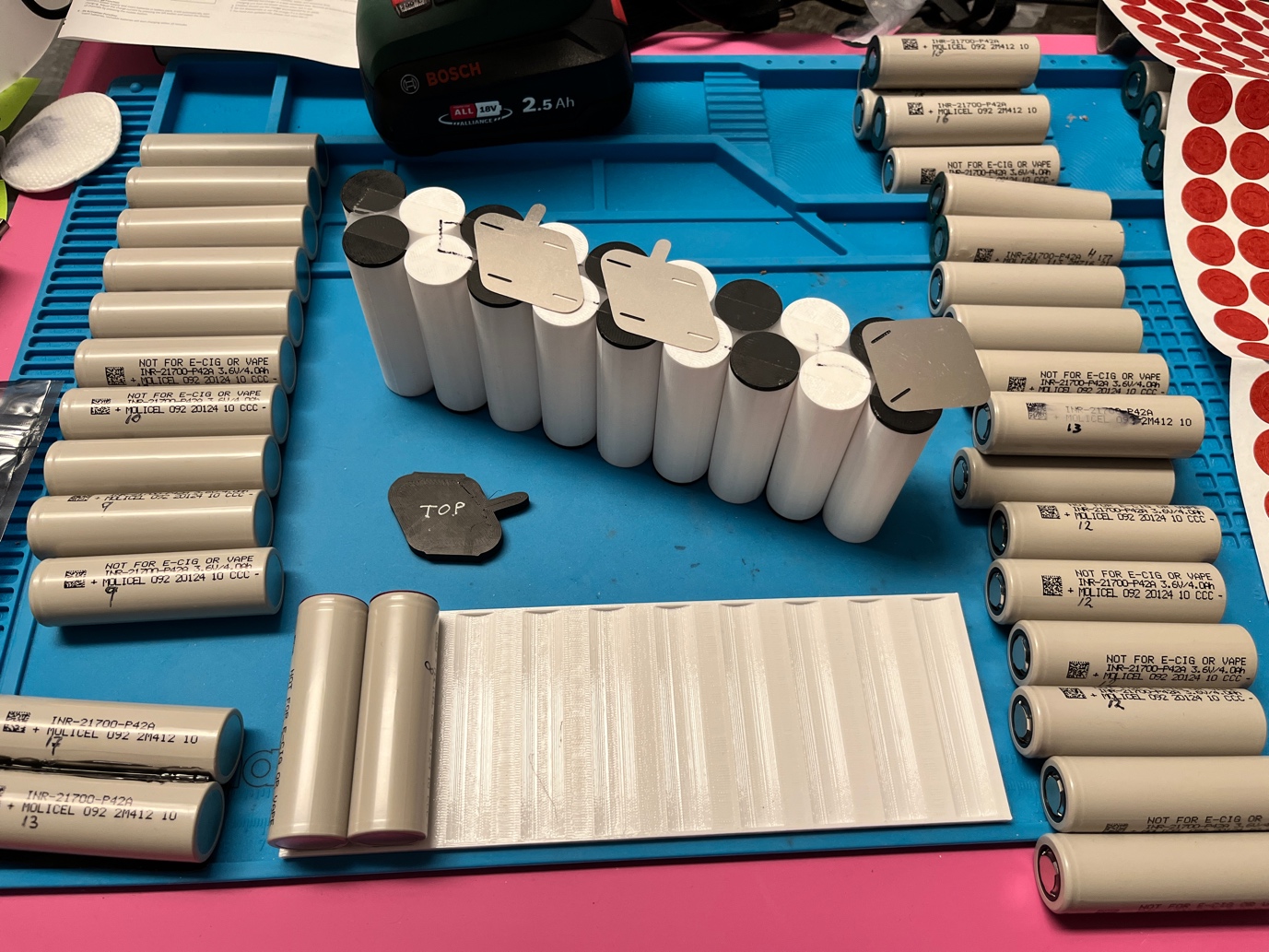
Be aware of the asymmetry in the fish paper patches, which is required because the pairs are lined up at an angle (60°). Since plus and minus sides are alternating between the pairs, you’ll need half of the patches with the 15mm part on the left, as in the first photo, and the other half with the 15mm part on the right. After this, we’ll have 16 pairs – 7 lefties, 7 righties, and 2 without fish paper. You’ll notice that the fish paper doesn’t perfectly stick to the batteries, as it’s quite thick, but that’s why we stuck the sharp fold into the hot glue. The fish paper’s main function is to insulate between the cells, and that will work fine. Once we group the pairs into two sides, we’ll apply some more glue between the pairs, and this will also keep the edges of the fish paper in place.
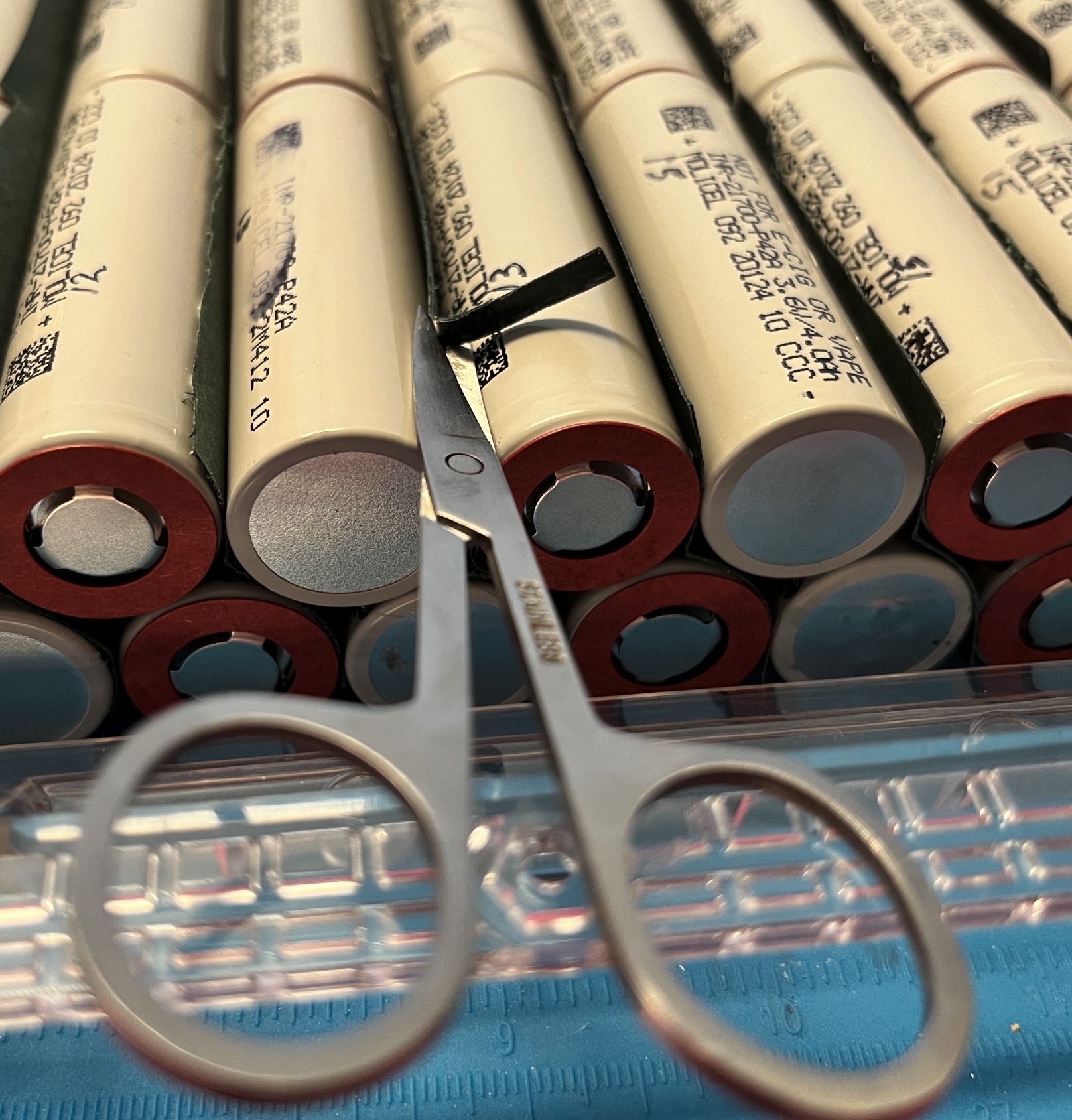
Next, put all pairs in the Torque Box, the way they will be in the box when the pack is ready. The pairs in the front and back row have their polarity aligned the same way, i.e. the positive pole of one row always touches the negative pole of the other row. If you have some spare batteries, I recommend putting in 6 extra batteries. The Torque box theoretically fits 19S2P, so if you put in 6 extra batteries, your pairs are pushed together just the way you want it before you glue the pairs together. Some of the fish paper patches may stick out a little, and I used nail scissors to remove such redundant paper (take care not to cut through the batteries’ plastic layer). On my next build, I will switch to making the patches a bit smaller: 35mm, folded into two sides: 15mm and 20mm. Then the scissors trimming should not be needed anymore.
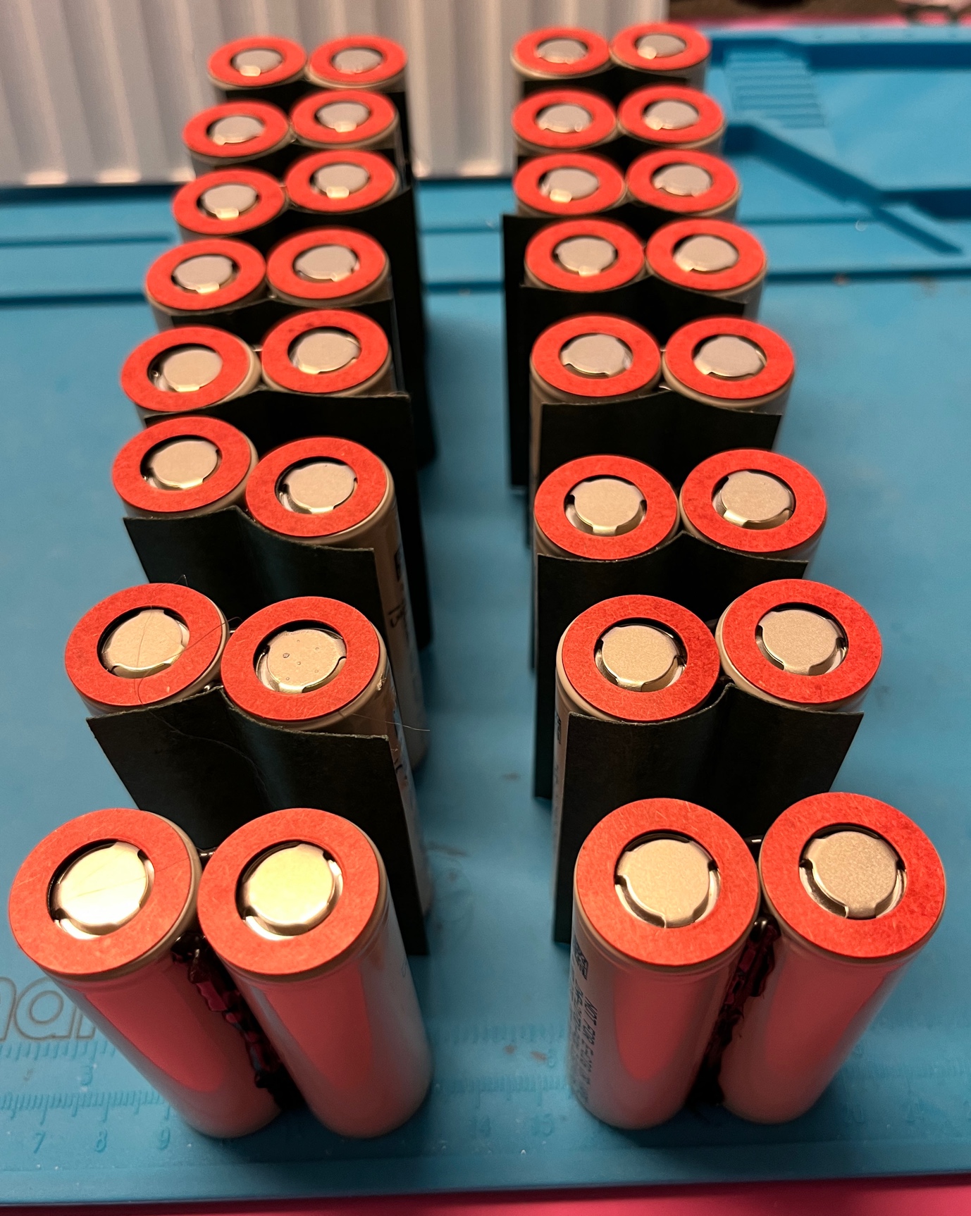
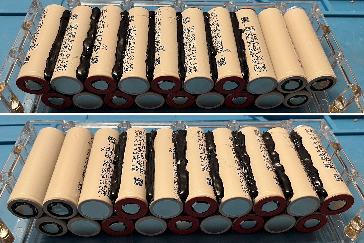
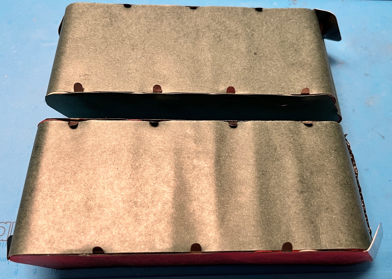
Now it’s time to glue the pairs together. Apply some glue to both sides of the fish paper if possible. Leave only one row of pairs in the Torque box, plus 3 filler batteries. If we leave both rows in the box, it becomes almost impossible to flip a row upside down without breaking the fresh glue. After applying the hot glue, carefully but the pairs on their side, put them in upside down, and put the 3 filler batteries on the other side of the box. Now you can glue the other side of the row. Repeat for the second row of pairs. This photo shows both sides of one row after having been glued.
Apply some Kapton tape around each row. On the long side, I stretch the tape over the cells, but on the ends, I make it follow the curves, to save some space for cables and box edges.
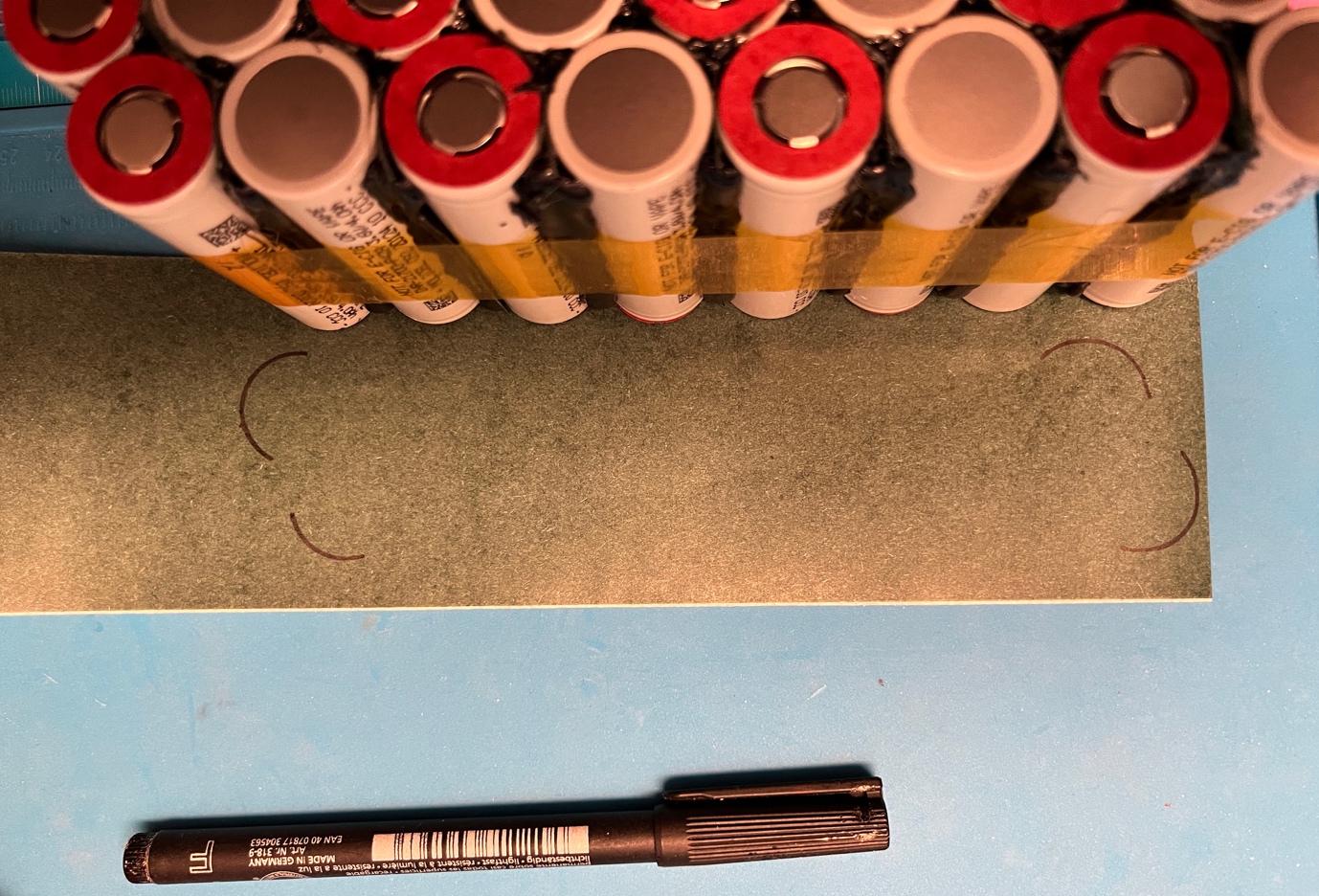
Prepare 4 covers out of fish paper, 1 for each side of each half of the pack. Put each side of each half pack on fish paper and mark the edges, twice. Theoretically, I laver of fish paper between the halves would be enough, but with each half being fully isolated it looks better, and 0,2mm extra is no big deal. I don’t follow the curves of the individual batteries – that way, it even provides some coverage of the lips for the BMS wires.
Now is a good time to prepare the nickel plates we’ll need. I used the precut plates from zbattery.solutions, but in my first pack, I cut them myself from a 30mm wide strip of 0.15mm thick pure nickel. Cutting these myself was a part of the job I didn’t enjoy at all, so I ordered the precut plates right after that. The planning for the plates looked like this.
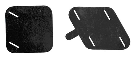
If you want to cut the plates yourself, here are the shapes. The ones with the lips are 30mm wide, so they can be cut right out of a 30mm strip. The ‘square’ ones are roughly 33x33mm, but I’m sure 30x33mm will work fine as well. The slits are for optimizing the currents while spot welding, but they are not strictly needed.
Spot welding
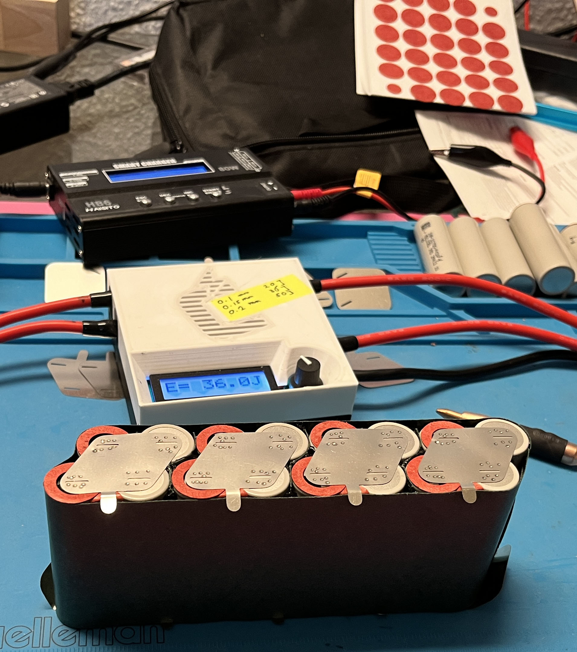
It’s time to do the actual spot welding. I am doing the plates with the lips first. Any poles that I am not welding, I put painter’s tape over, so I will not short anything by accident. Like I said, I am the cautious type. And I even use a multimeter to measure voltage between the poles before I even put a nickel plate on them. Any voltage over 0.05V means no-go. Such a tiny ghost voltage can sometimes occur between adjacent cells, and that’s no big deal. If you’re even more cautious than I am, you may want to measure the amperage between such cells.
On the Kweld, I use a 36J setting for 0.15mm nickel, and every weld is perfect that way.
I like to stick the inner dots of fish paper (leftovers from the insulation rings) underneath where the nickel lips for the BMS go, as an extra easy method to avoid shorts.
When all plates are welded, wrap each half of the pack in fish paper, and cover the top and bottom with the insulation you cut out earlier. Now you’ll have 2 clean looking halves of your battery pack.
This is a good time to put them into the Torque box and consider where you would like the BMS to go. Since the 16S is fairly small, it gives you the option to locate it on the side of the board (my preferred option, is it’s more roomy there) or rather in the tail of the board.
Time to turn the two halves into one pack. Initially I use narrower Kapton tape wrapped around the two halves, between the BMS lips, and then the wider Kapton tape around each half again. The nice thing about Kapton tape is that it adds strength, but has a neglectable thickness.
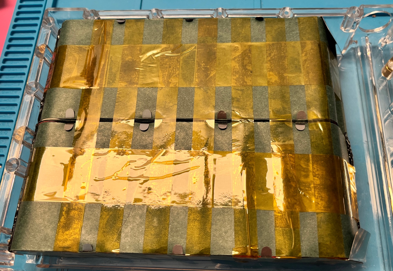
Now the two halves have to be connected (on the left side of the picture above). Last time I used two cables for that, but this time I’m using 0.15mm nickel. First I welded a 15mm strip underneath the battery plates, and then I added a 30mm strip on top, and also welded the two nickel strips together along the whole length.
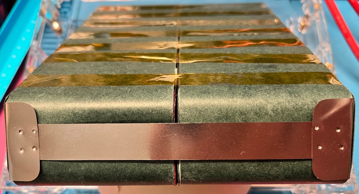
I covered that connection with another custom cut piec of fish paper (roughly 4mm wide), and hot glued the edges to make sure they stay in place on the rounded battery surface.
And wrapped both halves in wide Kapton tape one more to make double sure the fish paper stays in place.
At this point I counted the BMS lips and noticed that I only had 16 instead of 17, so I realized lip #8 was missing in the center of the pack. I lifted the fish paper on the negative side of that connected and welded a small strip of nickel diagonally, to avoid soldering the BMS wire on the thickest part of the pack. In retrospect, diagonally in the opposite direction would have been even better – then the wire and soldering would not have been at the very edge of the pack, but that edge will not be rubbing on anything in the box, so that’s no big deal. The final base pack looks like this.
Still missing are the wiring, the BMS, and the shrink wrap. The pack is now 41mm thick. The maximum thickness for the Torque box is 43mm, and if we squeeze the foam of the lid, 43.5mm, so we’re still good. The BMS wires plus the final shrink wrap will roughly 1mm, so we should still have room to also add some thin foam or silicon at the bottom of the box, to keep the battery pack from sliding.
The wires will go criss-cross – there’s no way around that, as the lips are switching between the left and right for each battery pair. One way is to do the crossings outside of the battery area, but that will make my wiring look like spaghetti, and I prefer a flat band cable. Having the crossings on the battery pack is OK asl well, as long as the crossings are always between battery pairs, where the fish paper can flex for extra room. If the crossings would occur elsewhere on the pack, they would add almost 2mm to the thickness of the pack. We might still be able to squeeze the pack in the box, but I don’t want to BMS wires rub against each other with that much pressure, as that could result in catastrophic shorts. So I used Kapton tape to keep the crossed wires in place at the ‘valleys’ between the battery pairs.
The result may look messier than the concept, so let me show you a quick drawing of the concept first.
Indeed, the initial result didn’t quite satisfy me.
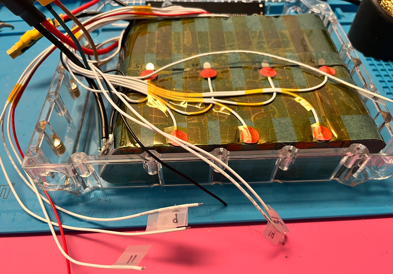
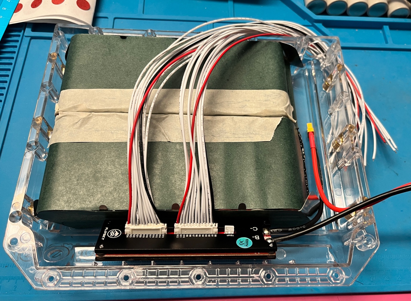
In my first build, the BMS was on the side of the board, right where the main battery connectors are, so the BMS cables were very short, and they were flat ribbons, so it made sense to do the crossovers on the battery, as in the drawing earlier. In this case, the BMS wires were all loose, and much longer, so I switched to the other method during the process.
Now the only thing missing was a PVC heat shrink. This is not strictly necessary, but I like the clean look of the pack that way, and it adds only a tiny bit of thickness.
Before I wrapped up the whole pack this way, I used a multimeter to double check the BMS wiring. Put the negative probe on the negative pole of the battery pack, and then check the voltage for all connections of the BMS connectors, starting from B0, working your way up. Make sure each next pin has roughly 3-4 V more than the previous one.
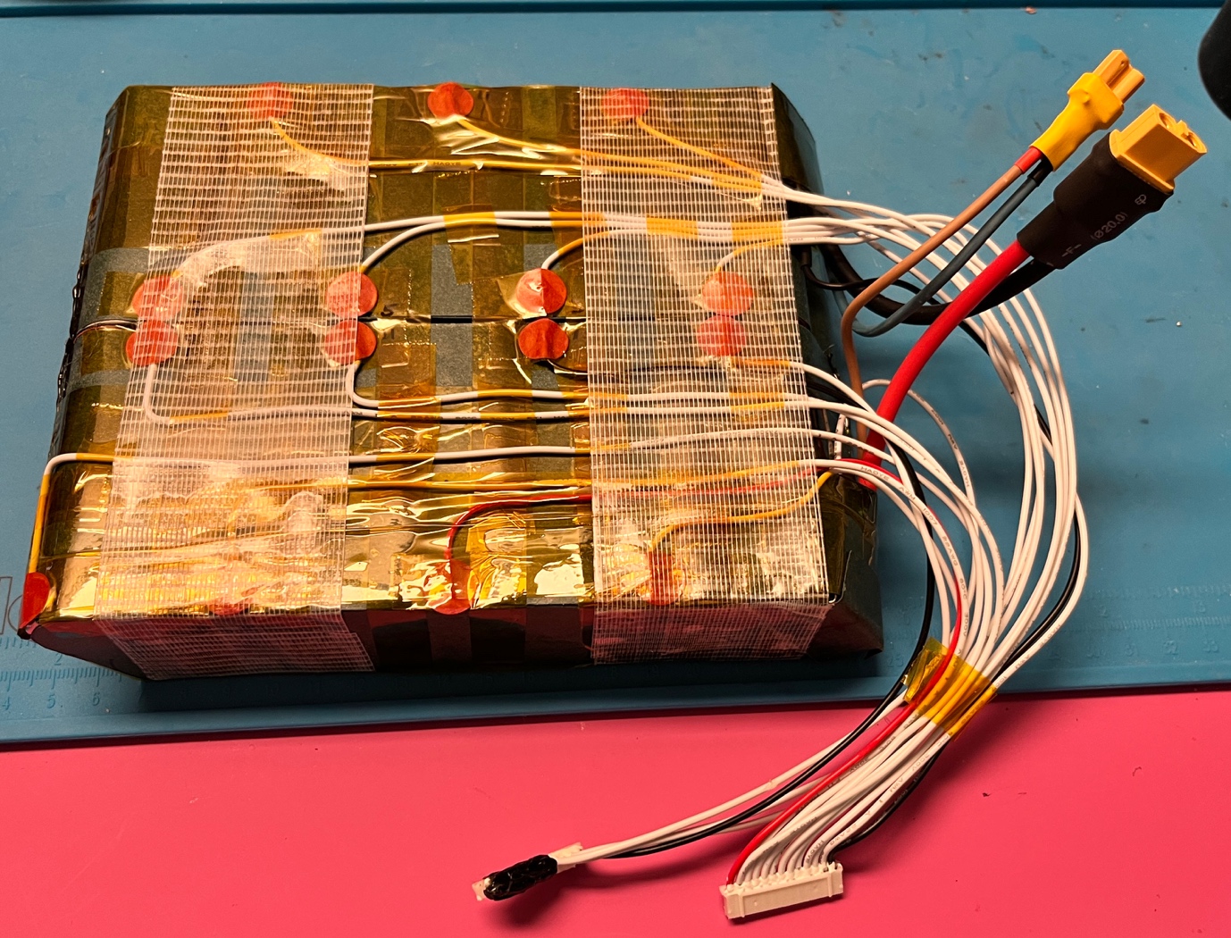
The wrapped pack looks like this (I also added the BMS temperature sensor, and neatened the BMS wires a bit with Kapton tape.
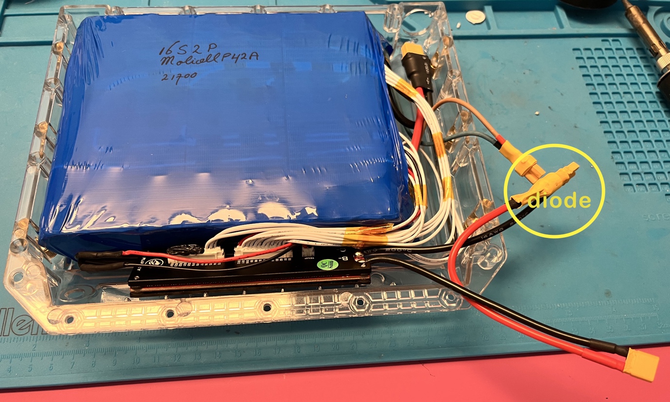
I also highlighted the diode, which I added in the positive wire of the BMS that goes to the charging port, to avoid possible battery shorts in the charge port, or shocks to my wet fingers when accidentally grabbing the charge port.
This concludes this battery building exercise. I will now wait for the harness to arrive, connect the cables, stuff some custom cut closed cell foam in the empty spaces, to keep the battery pack from sliding in the Torque Box, screw on the lid, and that should be all.
If you have feedback, questions, or improvements, please let me know (use the contact form on this site).
Cheers,
Jeroen
Tools and materials used here
I assume you’ll have some basic tools at home, such as screw drivers, pliers, a heat gun, and a soldering iron. Tools and materials that are more specific for this battery project are listed here, with possible sources.
Batteries (good source in Europe. I use Molicel P42A flat top)
Fish paper
https://www.amazon.de/-/en/BQLZR-Metres-0-2mm-Insulator-Gasket/dp/B07WZYTNF6
https://www.amazon.de/-/en/dp/B0CP1NJS15?th=1
Kweld (you can also buy a case for this device from their site, or 3D print your own)
https://www.keenlab.de/index.php/product/kweld-complete-kit/
Battery for Kweld
https://hobbyking.com/de_de/turnigy-battery-nano-tech-5000mah-3s-65-130c-lipo-pack-xt-90.html
XTAR Dragon VP4L Plus
https://www.amazon.de/-/en/VP4-PLUS/dp/B071Y7NJQC
Haisito HB6 charger (to charge the battery for the Kweld)
https://www.amazon.com/Charger-Battery-Balance-Discharger-Li-ion/dp/B08THFBN4Q
Precut nickel kit
https://zbattery.solutions/products/torque-pack-precut-nickel-kit
ZBMS
https://zbattery.solutions/products/zbms
https://de.aliexpress.com/item/1005005853933995.html?gatewayAdapt=glo2deu
Electrician gloves
https://www.amazon.de/dp/B005RFSJVU
Kapton tape
https://www.amazon.de/dp/B082ZLL5RC?th=1
XT30 plugs
https://www.amazon.de/gp/product/B07PC1YKVW
https://www.ebay.ch/itm/165217601601
XT60 plugs
https://www.amazon.de/gp/product/B09WZSWDD6?th=1
Blue shrink tube
https://www.amazon.de/sourcing-map-Schrumpfschlauch-Ersatz-Akkupack/dp/B09DGDXYQF
https://www.ebay.ch/itm/231950545915
Main wires (12 AWG)
https://www.amazon.de/gp/product/B07569DLLT
Charging wires (16 AWG)
https://www.amazon.de/gp/product/B075M5R4CF
Fixman tape
https://www.ebay.ch/itm/285137473432
Bosch AdvancedGlue Cordless Glue Gun 18 V
https://www.amazon.de/-/en/AdvancedGlue-Cordless-without-Battery-Seconds/dp/B0BG8ZP2JH
Hot glue black
https://www.amazon.de/-/en/Hei%C3%9Fklebe-Cartridges-Universal-adhesive-materials/dp/B00KPSFG9C
3D printable battery holder – handy during hot gluing
https://www.thingiverse.com/thing:6208273
 Bis auf weiteres gilt mindestens 2 Meter Abstand zwischen allen Teilnehmenden (inklusive Leiter). Der Abstand gilt vor, während, und nach Unterricht oder Tour (inklusive Pausen und Transport).